Part 2
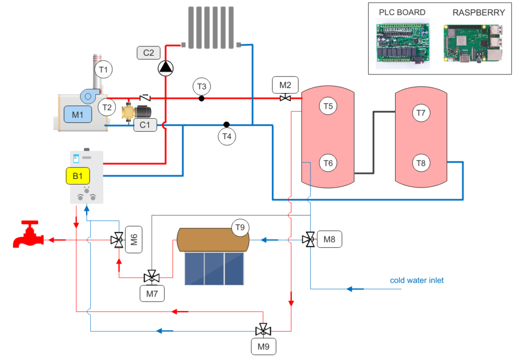
After introduction, let’s analyze the schematics of heating system. In the picture above you can see a simplified drawing representing the main blocks of the heating system.
Essentially we have two burners: a wood boiler and a gas boiler. First is the modern wood boiler, as described in the last post; the second is an addition boiler, intended as a support to the other, or as a backup when wood burner is off.
The water puffers store the surplus of heat from the wood boiler and deliver it when requested. The first one also ensure the production of sanitary water.
A solar panel supply hot water during summer and provide water pre-heating during cold season, or in case of bad weather.
The main components are:
- M1: wood boiler fan
- B1: gas boiler
- C1: wood boiler circulator
- C2: heating circulator
- M2,M6,M7,M8,M9: servomotors for valves
- T1: wood exhaust gas temperature thermocouple
- T2: wood boiler water temperature
- T3: hot water supply to heating temperature probe
- T4: return water from heating temperature probe
- T5,T6,T7,T8: puffer top and bottom temperature probes
- T9: solar panel water temperature probe
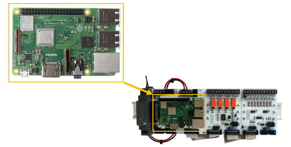
As hardware interface, I use some boards specifically designed to interface with Raspberry boards from Widgetlords. I particular this board provide a safe hardware layer interface between Raspberry GPIO pins to the rest of the network. Essentially it use s RPi SPI0 port for communication and allows to link additional boards to add more inputs and outputs. Very important, all these boards are industrial-grade to allow usage also in hard environments. So many boards can be daisy chained depending on needs: in my case I use 2 relay boards and an analog input board to measure temperatures. In total, I have 8 relays and 8 analogue inputs. My plans is to make even more I/O in the future, so I will buy additional boards and simply add to the system.
In the next part we will see some more details on hardware and interface.
Leave a Reply